Planimeters demystified
This initial part of this webpage contains link to a youtube video which shows an amazing thing: simple mechanical device is used to measure area of region with irregular shape. The rest of the page is devoted to the explanation - how it works and why, what is the mechanical and mathematical background of planimeters.
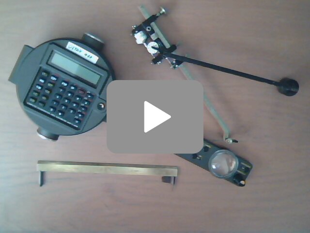
The video shows three planimeters in action. All of the planimeters are used to measure area of the same randomly drawn region. Thanks to Naslouchej mandarinkám for a pleasant music which gives background to this video. If you wonder how it works, if you cannot believe that it works, if you want to know more, then read the current web page. We try to explain the amazing fact that all you need to measure areas of arbitrary shape is line segment equipped with a wheel (moreover, sometimes the wheel may be missing) and some additional mechanical devices which govern the motion of this line segment.
On my first webpage dedicated to planimeters we followed briefly webpages of other authors and collected information how to explain planimeters with a bit of calculus. In the current article we give some simple geometric explanation to all of them. The advantage is, that we have unified theory for hatched planimeter, polar planimeter and linear planimeter.
Area swept by a moving line segment
Consider a line segment of fixed length with chosen normal unit vector. The segment is moving on the plane and some area is swept by this motion.
Any motion of the line segment can be approximated by motions of two special types (maybe huge amount of very small motions, but this does not matter):
- The normal vector has fixed direction, the swept area is a rectangle or parallelogram.
- One of the ends is fixed and the second follows a circle, the swept area is a circle sector.
Oriented (swept) area is defined as
- the swept area, if the line segment moves in the direction of normal vector and
- the swept area with negative sign, if the line segment moves in the opposite direction.
Oriented area is correctly defined in both special cases, when the swept area is either a parallelogram or a sector. Regions of general shape can be decomposed into union of regions of these two special types and the oriented area of the whole region is simply a sum of oriented areas of the components.
Below we show that the planimeter is simply a line segment which moves in the plane in a special manner and is equipped with one additional enhancement - integration wheel.
Consider a wheel perpendicularly attached to the line. Such a wheel, called integration wheel, naturally allows to decompose general motion to the direction of normal unit vector and the direction of the line. The distance traveled by the wheel is the projection of the motion to the direction defined by the normal vector. In both above special cases a simple geometric argument allows to relate the oriented swept area and the distance traveled by the wheel. This distance can be usually seen on a scale attached to the wheel.
The main tool is the following observation, which is not obvious, but can be proved by nothing more than simple geometry:
Planimeter theorem: If the line segment moves on the plane and the initial and final positions are equal, then the distance recorded by the integration wheel multiplied by the length of the segment equals to the oriented area swept by this segment.
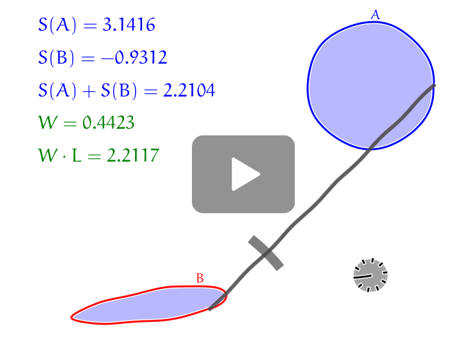
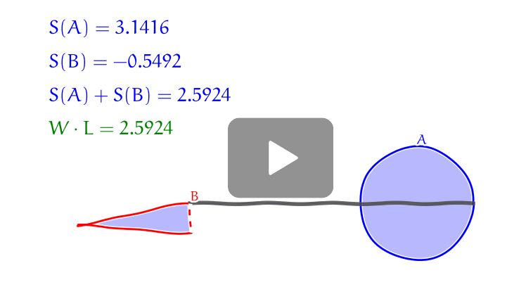
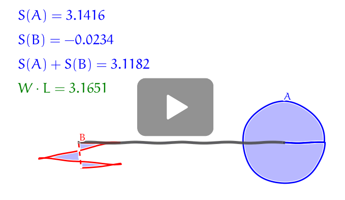
This fact is demonstrated on the computer generated animation above. Suppose that the normal vector to the line points left up when starting. Thus the oriented area of the region $A$ is positive and the oriented area of the region $B$ is negative. The oriented swept area between $A$ and $B$ is zero, since all points between $A$ and $B$ are swept once in a positive direction and once in a negative one. The difference of the areas of $A$ and $B$ (sum of oriented areas) is the total oriented area swept by the line.
As a consequence, if $S(A)$, $S(B)$, $W$ and $L$ are oriented area of $A$, oriented area of $B$, the distance recorded by the integration wheel and the length of the line segment, respectively, then Planimeter theorem states that the following relation hold. $$S(A)+S(B)=W\cdot L$$
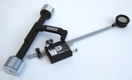
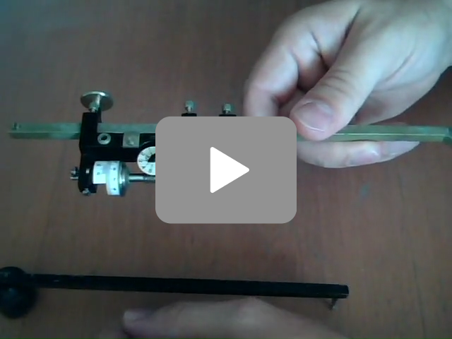 Integrating wheel which measures the normal component of the
motion. There is a scale and count register attached to the wheel. The
fact that the wheel is shifted a little bit from the line is
irrelevant.
Integrating wheel which measures the normal component of the
motion. There is a scale and count register attached to the wheel. The
fact that the wheel is shifted a little bit from the line is
irrelevant.
How to use the "Planimeter theorem"
The above formula can used to measure areas. Really, it is sufficient to trace the boundary of the region $A$ in such an manner that the area of $A$ is equal to the oriented area of $A$ and convert the above formula to $$S(A)=W\cdot L - S(B).$$ Now we just determine the quantities $S(B)$ and $W$ (the length $L$ is given by the construction of the planimeter).
Note that if one of the end points of the line segment traces the boundary of the region $A$, the second one still possess some degree of freedom. Thus the shape (and consequently area and oriented area of the region $B$) can be adjusted (within some bounds). As wee will see, different types of planimeters utilize this fact in different manner.
Linear planimeter
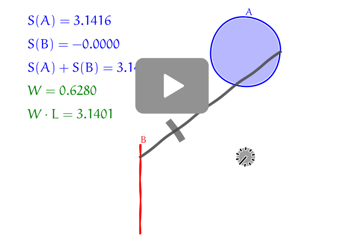
Fixing the point tracing the region $B$ to a line we ensure, that $S(B)=0$ and $$S(A)=W\cdot L.$$ Both $W$ and $L$ are known ($W$ can be read from a scale, $L$ can be changed to fit with the scale of the map) and it is easy to determine $S(A)$.
Typically, one of the end points can be fixed to a line by attaching it to a carriage which is not capable to move in other direction than straight forward and back.
Polar planimeter
The main idea is the same as for the linear planimeter, but the second end is fixed to a circle instead of the line. We have zero area of $B$, exactly as for linear planimeter.
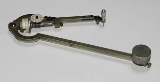
 For polar planimeter, one end of the moving line segment is fixed to a
circle and the second one traces the boundary of the area. The
fixation is managed by attaching the end to the end of another arm
with fixed second end. This arm is able to rotate around the fixed
pole and defines the circle.
For polar planimeter, one end of the moving line segment is fixed to a
circle and the second one traces the boundary of the area. The
fixation is managed by attaching the end to the end of another arm
with fixed second end. This arm is able to rotate around the fixed
pole and defines the circle.
Hatchet planimeter
The hatchet planimeter is similar to linear or polar planimeters: line segment of the length $L$ moves in the plane and one of the end points of the segment traces the boundary of the region.
The main idea of the hatchet planimeter is that the second end of the planimeter always moves in the direction of the line segment, in the direction of the planimeter. This forms the shape of region $B$. The motion described above can be ensured by special construction of the planimeter: we just have to prevent the second end of the planimeter from slipping to the left or to the right. This is typically achieved either by a hatchet-like blade or sharp wheel.
Let us put (at least in mind) the integration wheel to the end of the planimeter with hatchet blade. Thus we have the end of planimeter which cannot slip to the left or right and moves only in direction of the line segment (because of the hatchet blade) and the integration wheel which attached perpendicularly to the planimeter at this end. It is clear that such an integration wheel would not record any distance and this is the reason why a special construction of Prytz planimeter allows to throw the integration wheel away.
Have you seen the videos with using Prytz planimeter? Then you surely observed that when measuring is done the point which traces the measured region returns to the initial position and the second point is displaced from the original position. In other words, the planimeter does not return to the original position and thus the Planimeter theorem cannot be used. But this problem can be fixed easily.
Consider one additional motion which returns the planimeter to the initial position (i. e. one end remains in its position and the end with the blade moves along an arc, which corresponds to the dashed curve on the picture). Recall, that we initially intended to put the integration wheel to this end, but then rejected this idea, since such an integration wheel would not register anything. During our last move which returns the planimeter fully to the original position this wheel would record something. More precisely, it would record the length between the starting and end position of the end with the blade. Therefore, the integration wheel is not necessary again, since we have many other possibilities how to measure this distance. The most widely used method is to approximate the arc by line and measure the distance by a ruler.
The value $S(B)$ is simply neglected and replaced by zero, which is the most important source of error. The consequence is that using hatchet planimeter we get only approximation to the area.
Clever usage of the planimeter allows to make $S(B)$ relatively small.
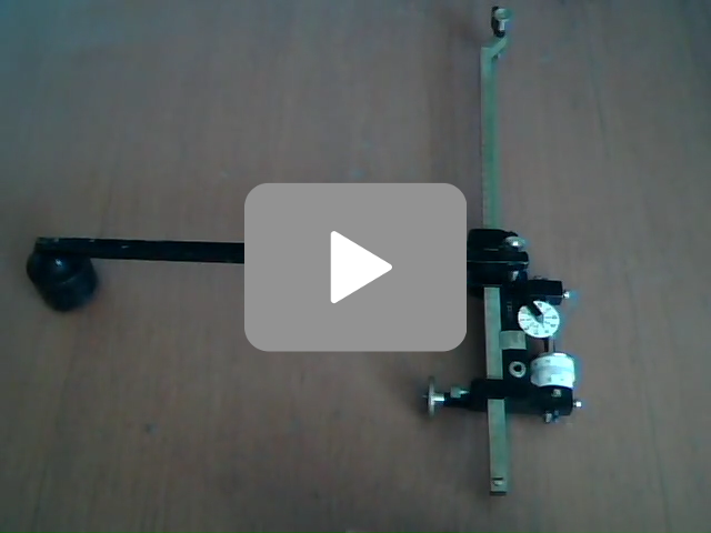
 Hatched planimeter: when one end moves, the second one always moves in the direction of the planimeter.
The influence of the initial position to the error of the hatchet planimeter
The point where we start and finish with the motion has significant influence to the (oriented) area of $B$. Compare the animation from the previous paragraph with the animation in this paragraph, where the measuring is started (and finished) at the point near the center of the circle. The trajectory of the second point is formed by three small curvilinear triangles, compared to one large triangle, if the measurement starts at the boundary. Moreover, two of these curvilinear triangles have opposite signs of oriented area.
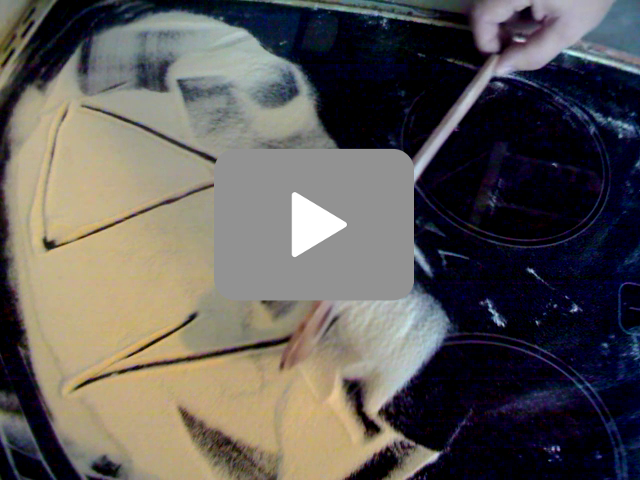 You can confirm that it is better to start measuring from the center
of mass by an experiment with cooker, wooden spoon and flour, as shown
on the video. I did not trace the hotplate too carefully (finished to
early) but the experiment still gives the same result as the computer
animation: The error of Prytz planimeter is smaller if we start
measuring near the center.
You can confirm that it is better to start measuring from the center
of mass by an experiment with cooker, wooden spoon and flour, as shown
on the video. I did not trace the hotplate too carefully (finished to
early) but the experiment still gives the same result as the computer
animation: The error of Prytz planimeter is smaller if we start
measuring near the center.
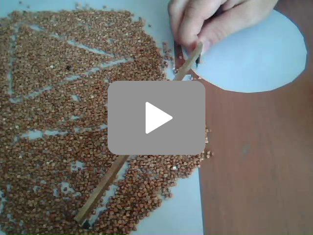 This experiment is similar to the previous one but on a surface of poor quality
-- table covered by buckwheet. Hatchet planimeter works fine here. The integrating
wheel of linear or polar planimeter would be inapplicable here.
This experiment is similar to the previous one but on a surface of poor quality
-- table covered by buckwheet. Hatchet planimeter works fine here. The integrating
wheel of linear or polar planimeter would be inapplicable here.
Final remarks
Note that most planimeters are designed to measure by enclosing area in clockwise direction. This has been used in the video with three planimeters. However in mathematics we usually consider clockwise direction as negative one. To make this explanation better accessible to the readers I followed the mathematically positive direction in animations on this webpage. Many other sites devoted to mathematical explanation of planimeters do the same.
Advantages of linear and polar planimeters compared to hatchet planimeter
- Linear and polar planimeters give exact values, not only approximations.
- Hatchet planimeter should not be used for very large or very small areas. In the first case the approximation of the circle by a line gives large error, in the second case there is small displacement between initial and final position.
Advantages of hatchet planimeter compared to linear and polar planimeters
- Hatchet planimeter is way simpler and robust.
- Hatchet planimeter is less sensitive to the quality of the smoothness of the surface being measured (meaning physical quality of the paper, which ensures, that the wheel moves fine)
Comparison of linear and polar planimeter
- With polar planimeter you cannot measure areas which are too large, since you are limited by the circle defined by the heavy pole and the arm which is attached to the arm with scale and tracer.
Literature
- Robert L. Foote: How Planimeters Work
- Bill Casselman, John Eggers: The Mathematics of Surveying: Part II. The Planimeter
- John Bryant,Chris Sangwin: How Round Is Your Circle?
- Robert L. Foote, Ed Sandifer: Area Without Integration: Make Your Own Planimeter
September 2015